
Last week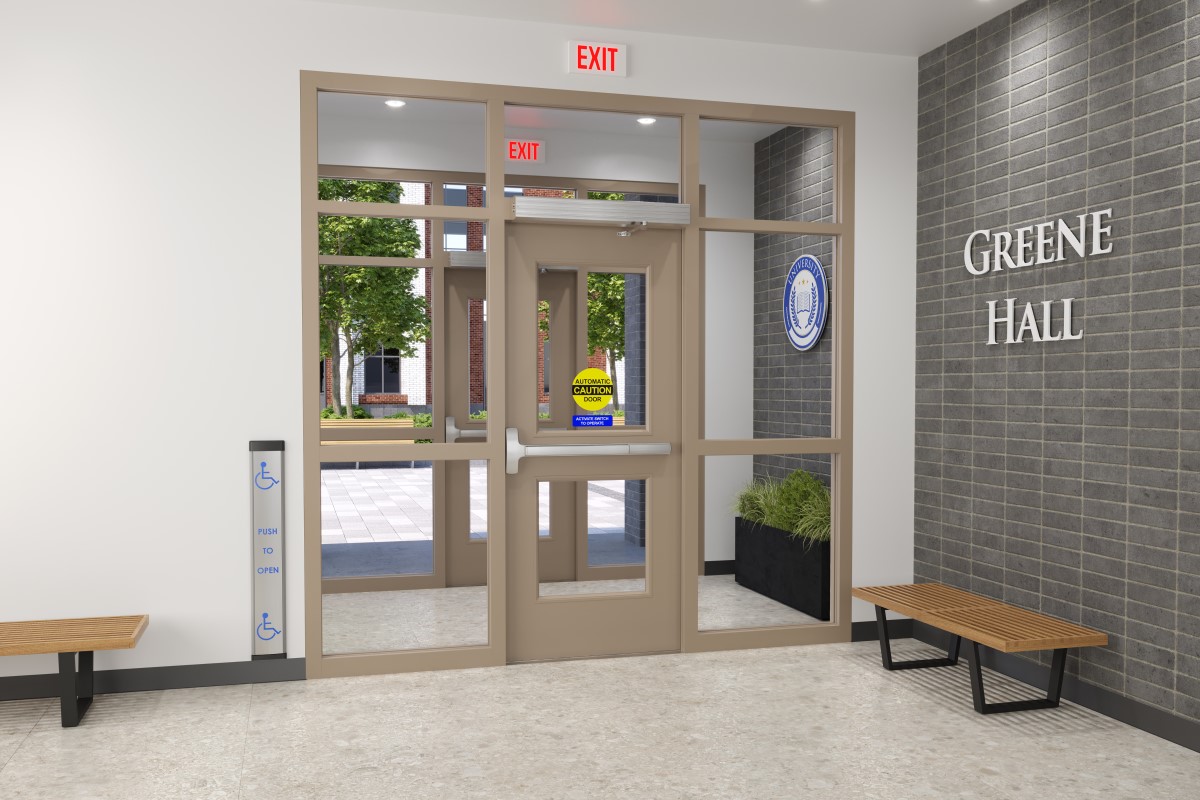 I posted about whether automatic operators are required by the International Building Code (IBC) for accessible public entrances on schools, which raised another Quick Question:
When a door that is secured to prevent unauthorized access from the outside is equipped with an automatic operator, how does the interface between security and accessibility function?
This has become a common application, but as with most door openings, this takes a bit of preplanning. If the proper hardware and operational description are not in place from the start, you could end up with a door that doesn’t unlatch for the automatic operator to open the door, or a locked door that allows free access when someone presses the button for the automatic operator.
It has been a while since I’ve written a hardware spec, so I asked Mark Kuhn of Allegion for a typical hardware set for this application, including the operational description explaining how it will work. The key is the electric latch retraction panic hardware (or latch retraction lockset), which retracts the latch before the door opens automatically, along with the relay in the power supply to coordinate the exterior actuator with the access control system. If someone does not present a valid credential, the exterior actuator will not open the door, but the interior actuator will always open the door automatically to allow someone to exit (the door can also be used manually for egress at all times).
The hardware set is below…is there anything that you would do differently? If the idea of specifying this hardware makes your head spin, you can always contact an Allegion specwriter for help. 😀
Hardware Group No. 36
For use on Door #(s): 100.1
Provide each OPENING with the following:
| QTY | DESCRIPTION | CATALOG NUMBER | FINISH | MFR | |
| 2 | EA | CONT. HINGE | 112HD EPT | 628 | IVE |
| 2 | EA | POWER TRANSFER | EPT10 CON | 689 | VON |
| 1 | EA | ELEC PANIC HARDWARE | SD-RX-QEL-9949-EO 24 VDC | 626 | VON |
| 1 | EA | ELEC PANIC HARDWARE | SD-RX-QEL-9949-NL-OP-110MD 24 VDC | 626 | VON |
| 1 | EA | INTERFACE BOX | JB7 AS REQUIRED | VON | |
| 2 | EA | SFIC MORTISE CYL. | 80-110 CAM AND CYLINDER RING AS REQUIRED | 626 | SCH |
| 1 | EA | SFIC RIM HOUSING | 80-129 | 626 | SCH |
| 3 | EA | SFIC CORE | 80-032 | 626 | SCH |
| 2 | EA | LONG DOOR PULL | 9266 72″ O | 630-316 | IVE |
| 2 | EA | OH STOP | 100S | 630 | GLY |
| 1 | EA | SURFACE CLOSER | 4040XP EDA | 689 | LCN |
| 1 | EA | PA MOUNTING PLATE | 4040XP-18PA | 689 | LCN |
| 1 | EA | CUSH SHOE SUPPORT | 4040XP-30 | 689 | LCN |
| 1 | EA | BLADE STOP SPACER | 4040XP-61 | 689 | LCN |
| 1 | EA | SURF. AUTO OPERATOR | 4642 | 689 | LCN |
| 1 | EA | WEATHER RING | 8310-801 | LCN | |
| 1 | EA | RELAY/DOOR SEQUENCER | 8310-845 | 689 | LCN |
| 2 | EA | ACTUATOR, TOUCH | 8310-853T | 630 | LCN |
| 2 | EA | DOOR SWEEP | 8198AA | AA | ZER |
| 1 | EA | THRESHOLD | 566A-MSLA-10 | A | ZER |
| 1 | EA | CREDENTIAL READER | MTB15 | BLK | SCE |
| 2 | EA | DOOR CONTACT | 7764 | 628 | SCE |
| 1 | EA | POWER SUPPLY | PS902 900-4RL 120/240 VAC | LGR | SCE |
| 1 | PROVIDE FACTORY POINT TO POINT WIRING DIAGRAMS AND RISER DIAGRAMS | ||||
| 1 | NOTE | SEALS BY DOOR MFR |
OPERATIONAL DESCRIPTION: DOORS NORMALLY CLOSED AND LOCKED. PRESENTING VALID CREDENTIAL TO READER MOMENTARILY RETRACTS PANIC DEVICE LATCHES AND MOMENTARILY ENABLES EXTERIOR ACTUATOR BUTTON. PUSHING ENABLED EXTERIOR ACTUATOR BUTTON SIGNALS AUTOMATIC OPERATOR TO MOMENTARILY OPEN DOOR. INTERIOR ACTUATOR ALWAYS ENABLED. PUSHING INTERIOR ACTUATOR BUTTON SIGNALS AUTOMATIC OPERATOR TO MOMENTARILY OPEN DOOR. PANIC DEVICE LATCHES ALSO CAPABLE OF BEING ELECTRONICALLY DOGGED DOWN (I.E. PUSH/PULL MODE) AS DESIGNATED BY ACCESS CONTROL SYSTEM SCHEDULE. EXIT DEVICES LATCH AND LOCK WITH ACTIVATION OF SECURITY SYSTEM. DOOR REMAINS LOCKED TO PREVENT ACCESS UPON POWER LOSS. DOOR ALLOWS FREE EGRESS AT ALL TIMES.
You need to login or register to bookmark/favorite this content.


WOW…it must have taken a hardware GURU to write that set 😉
When the hardware set requires a second page… 🙂
It’s not an Allegion part, but I used the BEA BR2-900 as the “brains” of systems like this to facilitate access control from the secure side and free egress from the inside.
The Allegion 8310-845 seems to be a re-labeled BEA BR3-X, which is my usual go to for this situation.
Thanks for showing me the BEA BR2-900 as a 900Mhz option for when I have wireless buttons on both sides.
Retired here but this was a common application. We did several things to make all this work together
The operator had to have a two-channel receiver so that the inner and outer buttons were independent. The outer button would not even try to open the door if it was locked. The inner button would always allow egress.
Secondary consideration. All of our University perimeter doors were alarmed after hours. There was always a motion detector above the door to shunt the alarm so that egress would not report an intrusion. Card access would allow authorized entry and shunt the alarm also.
Mag locks were very rare and needed special attention. The motion detector would shunt the alarm but would NOT release the mag lock. That was handled by a switch in the exit device or sensor bar and by the auto operator. If a “bad guy” was outside and someone walked past the interior of the door, we did not want the sensor to unlock the door and let him in.
Ff inside motion detector is used only to shunt the alarm. rather let the switch in exit device do both – shunt the alarm and release mag lock,
Holy crap…
Do we need electric latch retration on both devices?
Sorry – I missed this question! I noticed that too and I assumed that the end user wanted electric latch retraction on both leaves to leave the doors unlocked at certain times.
– Lori