
This article was published in the July 2014 issue of Construction Specifier. It is currently posted on ConstructionSpecifier.com.

Panic hardware has traditionally been required to operate with no more than 15 pounds of force. New requirements limit the operation of door hardware to a maximum of 5 pounds.
The 2010 Americans with Disabilities Act (ADA) Standards for Accessible Design went into effect in March 2012, but there are several requirements that continue to surprise architects and specifiers.
This article examines four particular changes related to doors on an accessible route:
- door hardware must now operate with 22.2 N (5 lb) of force—a limit most panic hardware does not meet;
- any low-energy automatic operators actuated by a motion sensor must meet the safety requirements for a full-powered automatic operator—possibly including safety mats and guide rails;
- bottom rails of manual swinging doors must be at least 254 mm (10 in.) high, and no hardware may protrude from the push side within the bottom 254 mm (10 in.); and
- automatic operators on doors that do not provide proper egress-side maneuvering clearance for a manual door must have standby power.
Some of these issues are specific to the 2010 ADA, while others are also addressed by International Code Council (ICC) A117.1, Accessible and Usable Buildings and Facilities. This standard is referenced by the International Building Code (IBC), International Fire Code (IFC), and National Fire Protection Association (NFPA) 101, Life Safety Code, for doors on an accessible route.
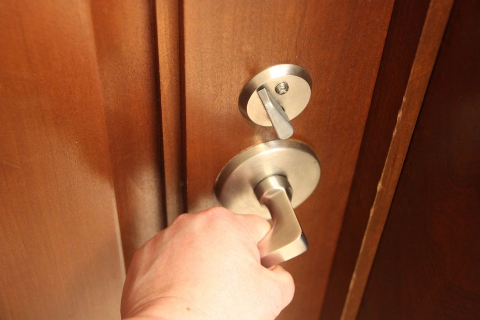
Operable force for door hardware
A change submitted for the next edition of ICC A117.1 would limit rotational force to 28 inch-pounds, and operation by a pushing-pulling motion to 15 pounds.
An editorial change was made to the 2010 ADA to limit the operable force for door hardware to 22.2 N (5 lb). Editorial changes are normally used to address errors or make clarifications that do not affect the scope or application of the code requirements. These changes do not go through the normal code development process (i.e. committee hearings and opportunities for public comment). In other words, this change was unexpected.
In the 1991 edition of ADA, door hardware was required to have:
a shape that is easy to grasp, and does not require tight grasping, tight pinching, or twisting of the wrist to operate.
This is the same language currently included in A117.1. No force limitation was mentioned with regard to the operation of hardware.
The 2010 edition of ADA changed the section that applies to door hardware, by referring to Paragraph 309.4–Operation:
Operable parts shall be operable with one hand and shall not require tight grasping, pinching, or twisting of the wrist. The force required to activate operable parts shall be 5 pounds (22.2 N) maximum.
By referencing Paragraph 309.4, a limit for the operational force of hardware was established.
Conflicts and clashes
This change created conflicts with other codes and standards, and even within the 2010 ADA standards. For example, in ADA, section 404.2.9 addresses door and gate opening force – the force required to physically open the door. This section states the 22.2-N (5-lb) limit on opening force does not apply to the force required to release the latchbolts. This implies the allowable force required to release latchbolts could be greater than the 22.2-N (5-lb) opening force. The U.S. Access Board unofficially acknowledged there was a conflict between the opening force section and the operational force required by reference, but to date the standards have not been modified.
Another conflict lies with IBC, IFC, and NFPA 101, for which panic hardware is required to operate with a maximum of 66 N (15 lb) of force to release the latch. In an attempt to establish a level of operational force aligned with other codes and standards, a change proposal was submitted for the 2015 edition of ICC A117.1. If approved, the proposal would establish a limit of 66 N (15 lb) maximum for hardware operated by a forward, pushing, or pulling motion, and 3 N-m (28 inch-pounds) maximum for hardware operated by a rotational motion.
Additionally, the 2013 California Building Code (CBC) includes language virtually identical to the 2010 ADA operational force requirements, and requires hardware to operate with 22.2 N (5 lb) of force, maximum. However, the code contains conflicting language in Section 1008.1.10–Panic and Fire Exit Hardware, which requires panic hardware to operate with a maximum of 66 N (15 lb) of force.
Given the change to CBC and the delay in addressing the conflict within the 2010 ADA standards, there are projects where the 22.2-N (5-lb) limit is being enforced for both lever-operated and panic hardware. For each project, a decision must be made regarding whether to use hardware meeting the requirements of IBC (and its referenced standard, ICC A117.1), or whether to specify hardware that meets the 22.2-N (5-lb) limit to avoid a conflict with ADA standards.
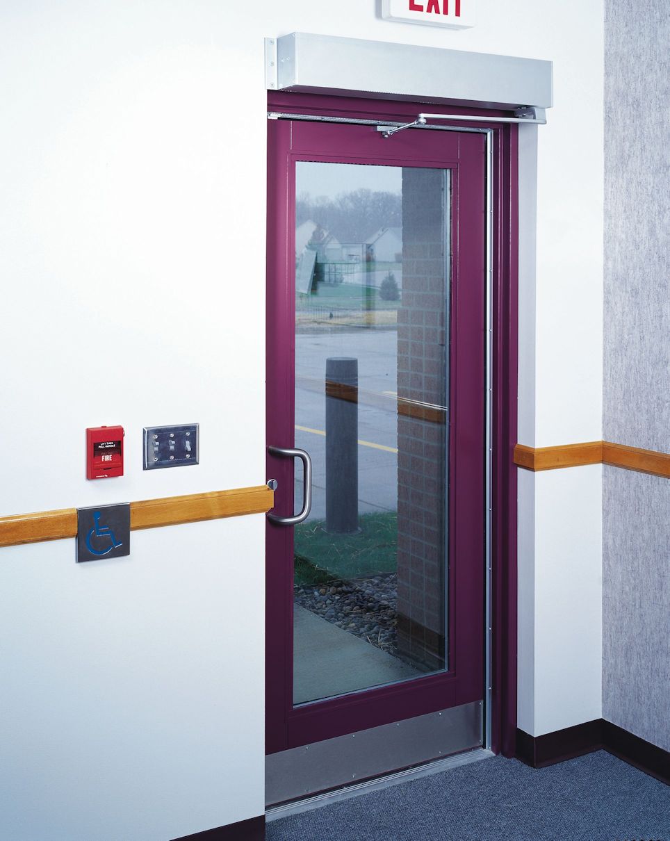
A low-energy automatic operator must be actuated by a knowing act, such as this wall-mounted push button, or must comply with the requirements of ANSI/BHMA A156.10.
Actuators for automatic operators
From a codes and standards perspective, there are three basic types of automatic operators for swinging doors:
- power-assist;
- low-energy; and
- full-power.
Power-assist operators reduce the opening force so the door can be manually opened more easily, but some manually applied force is still necessary. These operators are usually activated by pushing or pulling the door, although occasionally a wall-mounted actuator is employed to reduce the force only for users who need that feature.
Low-energy operators are often used when the door will be opened manually by some users and automatically by others. The doors are subject to limitations on opening speed and force to curtail the generation of kinetic energy and the potential for injury. Further, they must be operated by a ‘knowing act,’ as described later in this article.
Due to these limits, most doors with low-energy operators are not required to have safety sensors, control mats, or guide rails. Both power-assist and low-energy operators must comply with American National Standards Institute/Builders Hardware Manufacturers Association (ANSI/BHMA) A156.19, Power-assist and Low-energy-operated Doors.
Full-power operators are typically found on high-use openings like the entrance to a grocery store or department store. These operators are not subject to the same restrictions on speed and force, and safety sensors or control mats and guide rails are required to prevent the doors from opening if someone is in the path of the door swing. Full-power operators must comply with ANSI/BHMA A156.10, Standard for Power-operated Pedestrian Doors.
The 2002 edition of ANSI/BHMA A156.19 introduced a requirement for power-assist and low-energy-power-operated doors to be activated by a ‘knowing act,’ and this requirement carries forward to the 2013 standard. The ‘knowing act’ method may be:
- a push-plate actuator or non-contact switch mounted on the wall or jamb;
- the act of manually pushing or pulling a door; or
- an access control device like a card reader, keypad, or keyswitch.
The A156.19 standard also makes recommendations regarding the mounting location of a knowing act switch. Actuator switches should be located:
- a maximum of 3.7 m (12 ft) from the center of the door (0.3 to 1.5 m [1 to 5 ft] is preferred)—when further, the recommended increased hold-open time is one additional second per 0.3 m (1 ft) of distance;
- where the switch remains accessible when the door is opened, and the user can see the door when activating the switch;
- in a location where the user would not be in the path of the moving door; and
- at an installation height of 864 mm (34 in.) minimum and 1219 mm (48 in.) maximum above the floor.
The 2010 ADA and ICC A117.1 contain requirements pertaining to the actuators for automatic doors in addition to what is included in the referenced standard. Clear floor space for a wheelchair must be provided adjacent to the actuator, and beyond the arc of the door swing. The mounting height is variable, depending on the reach range associated with the switch location. However, the range recommended by ANSI/BHMA standards is acceptable for most applications. Actuators must not require tight grasping, pinching, or twisting of the wrist to operate, and the operating force is limited to 22.2 N (5 lb) maximum.
Stepping into the field of a motion sensor is not considered a knowing act. If automatic operation via a motion sensor is desired, automatic doors must comply with the standard for full power operators—ANSI/BHMA A156.10, instead of A156.19. This means even though the door may have a low-energy operator, it has to meet the same requirements as a full-power operator, including the safety sensors or control mats and guide rails.
Typically 762 mm (30 in.) high, guide rails are required on the swing side of each door. For some locations, the need for guide rails may mean motion sensor operation is not feasible. When certain criteria are met, walls may be used in place of guide rails. When doors are installed across a corridor, guide rails are not required if the distance between the wall and the door in the 90-degree open position does not exceed 254 mm (10 in.)

Some jurisdictions require actuators mounted in two positions, or a vertical bar actuator which will allow the door to be operated by a hand/arm or a crutch, cane, or wheelchair footrest.
The 2013 California Building Code requires two push-plate actuators at each actuator location—one mounted between 178 and 203 mm (7 and 8 in.) from the floor to the centerline, and the other mounted between 762 and 1118 mm (44 in.) above the floor. Vertical actuation bars may be used in lieu of two separate actuators, with the bottom of the bar at 127 mm (5 in.) maximum above the floor and the top at 889 mm (35 in.) minimum above the floor.
Actuators must be in a conspicuous location, with a level and clear ground space outside of the door swing. The minimum size for push plates is 102 mm (4 in.) in diameter or 102 mm square, and the minimum operable portion for vertical actuation bars is 51 mm (2 in.) wide. Both types of actuators must display the International Symbol of Accessibility.
While all these requirements have the same basic intent, it is best to check state and local codes to see which standard has been adopted, and what the specifics are in reference to actuators for automatic operators. It is important to verify the actuator type/quantity, location, and any additional requirements. Further, one must keep in mind additional safety features—including sensors and guide rails—may be required for low-energy operators actuated by a motion sensor.
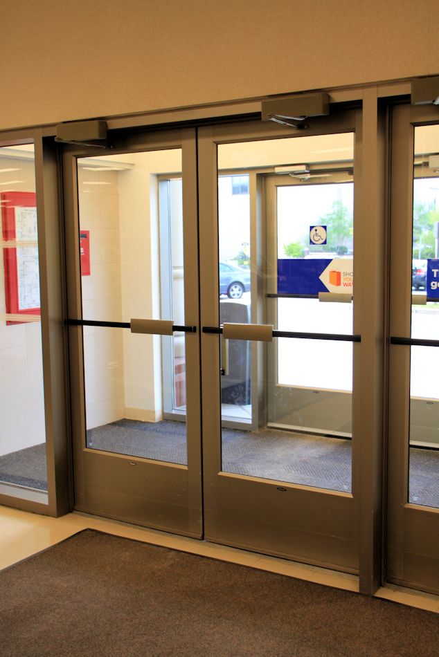
Standby power for automatic operators
The 2010 Americans with Disabilities Act includes revisions to the section on automatic doors with regard to clear width and maneuvering clearance. (These have not been included in A117.1 to date.) The ADA standards read:
404.3.1 Clear Width. Doorways shall provide a clear opening of 32 inches (815 mm) minimum in power-on and power-off mode. The minimum clear width for automatic door systems in a doorway shall be based on the clear opening provided by all leaves in the open position.
404.3.2 Maneuvering Clearance. Clearances at power-assisted doors and gates shall comply with 404.2.4. Clearances at automatic doors and gates without standby power and serving an accessible means of egress shall comply with 404.2.4.
EXCEPTION: Where automatic doors and gates remain open in the power-off condition, compliance with 404.2.4 shall not be required.

If an automatic operator is installed to overcome a maneuvering clearance issue on the egress side, the 2010 ADA requires standby power for the operator. Photo: SAS Architects
According to both accessibility standards and egress requirements, most doors have to provide at least 815 mm (32 in.) of clear opening width. For pairs of doors, at least one leaf has to provide 815 mm clear (32 in.). The aforementioned Paragraph 404.3.1 states the required clear opening width must be provided “in power-on and power-off mode.” The clear opening’s full width is considered—for example, a 1.5-m (5-ft) pair of automatic doors would provide sufficient clear width even though neither leaf meets the minimum clear width for a manual door.
Maneuvering clearance for manual doors is addressed in Section 404.2.4 of the 2010 ADA. This section establishes the minimum space around the door needed by a wheelchair user to manually operate the door. The previously cited Paragraph 404.3.2 requires power-assisted doors and gates (manually operated but with reduced opening force) to have the same maneuvering clearance as manual doors. Automatic doors and gates serving an accessible means of egress without standby power would also need the required maneuvering clearance. Therefore, automatic doors and gates with standby power do not need the maneuvering clearance that would be required for a manual door.
If an existing door serving an accessible means of egress does not have the required maneuvering clearance and an auto operator is added to overcome that problem, the operator needs to have standby power (unless the door stands open on power failure per the exception). This applies to doors part of a means of egress that must be accessible in an emergency, and is intended to avoid entrapment of a person with a disability if there is a power failure. The standard does not include a requirement for how much standby power must be provided.
It is important to keep in mind automatic operators on fire-rated doors are required to be deactivated upon fire alarm. Therefore, an automatic operator with standby power should not be used on a fire-rated door to overcome maneuvering clearance problems because it will not be functional when the fire alarm is sounding.
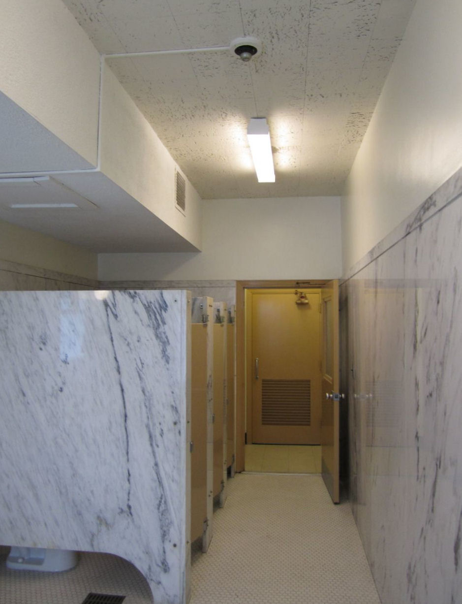
Flush bottom rails
Manual doors on an accessible route must have a smooth surface on the push side with no protruding hardware within 10 inches of the floor or ground.
For many years, ICC A117.1 has included a requirement for a 254-mm (10-in.) high flush bottom rail on manual doors, and this requirement is now included in the ADA standards. The text of both standards is similar, except ADA also addresses existing doors. (This requirement appears in the “Manual Doors” section of both publications, so it does not apply to automatic doors.)
The purpose is to avoid projections that could catch a cane, crutch, walker, or wheelchair and inhibit passage through the door opening, so the requirement applies to the push side of the door only. The 254-mm (10-in) measurement is taken from the floor or ground to the top of the horizontal bottom rail, extending the full width of the door. Prior to the 2003 edition of A117.1, the required dimension was 305 mm (12 in.).
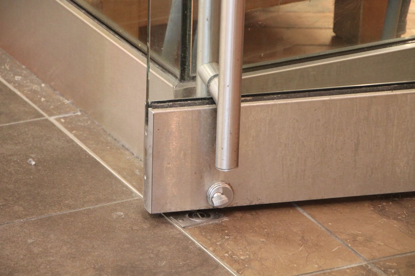
The standards require the surface of swinging doors and gates within 254 mm (10 in) of the finish floor or ground to have a smooth surface on the push side that extends the full width of the door or gate. Narrow bottom rails and protruding surface bolts, surface vertical rods, kick-down stops, and full-height door pulls installed on the push side of the door would not comply with this requirement for a 254-mm (10-in.) high smooth surface. Horizontal or vertical joints in this surface must be within 1.6 mm (1/16 in.) of the same plane. If a kick plate is added to a door with a narrow bottom rail to resolve this problem, the cavity between the kickplate and the glass or recessed panel must be capped.
There are several exceptions to this requirement. Sliding doors are not required to comply. Tempered glass doors without stiles are not required to have a 254-mm (10-in) bottom rail (if the top of the bottom rail tapers at 60 degrees minimum from the horizontal), but protruding hardware is not allowed in the 254-mm (10-in) high area. Doors that do not extend to within 254 mm (10 in) of the finish floor or ground are also exempt.
Protruding hardware within the bottom 10 inches of a door opening could inhibit passage through a door opening by catching a crutch, cane, walker, or wheelchair.
As outlined in ADA, existing doors are not required to provide the 254-mm smooth surface, but if kick plates are added to widen the bottom rail, the gap between the top of the plate and the glass must be capped. Existing doors are not addressed by A117.1, which is typically used for new applications as referenced by IBC. Now the standards are consistent, and increased awareness and enforcement of this requirement seem likely.
Conclusion
With regard to these changes in the Americans with Disabilities Act standards, some accessibility requirements are not prescriptive and enforcement varies by jurisdiction. Therefore, it can be difficult to apply the standards, especially when conflicts exist. Additionally, some states have established their own accessibility standards. Following the most stringent requirements can help to avoid problems, and the local authority having jurisdiction (AHJ) can also provide assistance to determine what is required.
You need to login or register to bookmark/favorite this content.


We have also been having issues with the heights of lites (see the following) and with the height of dutch door shelves.
“Reference: New ADA Section 404.2.11 states, “” Vision Lights, Doors, gates, and side lights adjacent to doors or gates, containing one or more glazing panels that permit viewing through the panels shall have the bottom of at least one glazed panel located 43 inches (1090 mm) maximum above the finish floor.”” EXCEPTION: Vision lights with the lowest part more than 66 inches (1675 mm) from the finish floor or ground shall not be required to comply with 404.2.11.
Hi Deb –
That requirement has been in ICC A117.1 for a while, but is new to the ADA. It’s creating some coordination problems with lite/lock conflicts. I’d love to know what is emerging as the preferred lite size / location and whether the hardware location is affected.
– Lori
In our area these codes somehow don’t seem to apply to Aluminum Doors. Is this typical in other areas??
I haven’t seen a difference in my area…with very few exceptions the standards apply regardless of the door material.
From an AADAM perspective I have always been taught KNOWING ACT or UNKNOWING ACT so I have always treat a door with a motion sensor as an UNKNOWING ACT hence I have always treated as 156.10
I was in a meeting recently and someone told me I can not use SVR’s anymore in MA because MAAB has adopted this new rule, but when I go on the MAAB website I find old reference only. 5
I don’t know of Mass adopting anything other than 521 CMR, and I don’t see the 10″ requirement in 521 CMR.
Manual doors require a 10″ high flush bottom surface, but are not required on automatic swing doors. What if the door is within the required path of egress AND there is adequate maneuvering room (thus, not requiring standby power)- does it then need a 10″ bottom clear surface???. At that point, it is essentially a manual door within the path of egress!
That’s an interesting question. I have not heard of any AHJs applying the 10″ flush bottom requirement to automatic doors – even those that are used manually for egress.
I have the same question and was assuming that push/pull hardware needs to be above the 10″ smooth surface zone if the door is not on standby power. Have we been overthinking this? As of 2018, have any AHJs acquired an opinion on this?
Hi Marta –
I haven’t seen anything specific from the AHJs on this, but if it’s an automatic door then the requirement for the 10-inch smooth surface at the bottom shouldn’t apply since this paragraph is only in the manual door section of the standard.
– Lori
We have multiple sets of manual double doors in our building. On the push side, they all have vertical rods that extend down to the floor from the panic bar (and up to the frame), these are what “latch” the door, as there is no center mullion. Am I right, ADA no longer allows these? If so, are we grandfathered, or will we need to change them out (they are in egress pathways)? If we have to change them….wow, these doors are only three years old!!!
Hi Beth –
ICC A117.1 (the accessibility standard referenced by the IBC and NFPA 101) has required the 10″ flush area at the bottom of the door for several editions – it used to be 12″ instead of 10″. It was just added to the ADA in the 2010 version. If your state uses A117.1, then it’s likely that these doors were non-compliant when they were installed. I haven’t seen retroactive enforcement of this requirement – it was not widely enforced or even noticed until it went into the ADA. There are millions of existing doors that do not comply, so whether you need to make a change would be up to your AHJ. If you do decide to change them, you may be able to remove the bottom rod and latch and install an auxiliary fire pin if the doors are fire rated. Removing the bottom rod and latch can sometimes impact the security of the opening, so I don’t usually use less-bottom-rod devices on exterior doors.
– Lori
Assume this entrance setup: one pair of exterior doors, both leafs operated; and one pair of vestibule doors, both leafs also operated. How many actuators are required? And where are they placed? (i.e., one actuator per door leaf? one actuator per pair? one at the exterior, one at the interior, one in the vestibule?)
Hi Laurie –
If both leaves of each pair are operated simultaneously, then I would use one actuator per pair. The doors could be set up to be sequentially operated, so that pushing the interior actuator opens the interior doors and then the exterior doors a few seconds later (the opposite would happen with the exterior actuator). I usually specify one additional actuator for the vestibule, that is split so one side controls the exterior doors and the other controls the interior.
– Lori
But does code actually require an actuator in the vestibule?
Hi Maria –
The standards do not specifically state that an actuator is required in the vestibule, but some AHJs do require it to avoid entrapment for people who can not open the doors manually.
– Lori
I’m wondering if doors with auto operators need to comply with 43” maximum above finished floor. If someone have come across this issue please share.
Is your question whether the vision lights have to be no more than 43 inches above the floor on automatic doors? If yes, that’s a really good question. I had not noticed before, but the vision light paragraph of the accessibility standards is in the manual door section, and is not repeated in the automatic door section. So I would say that technically the requirement does not apply to automatic doors.
– Lori